Finder Plus
Product Details:
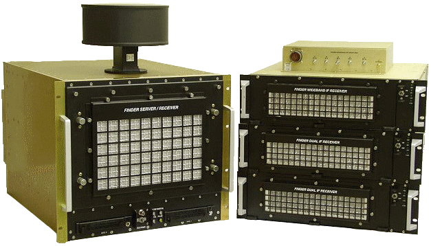
Aeronix’s FinderPlus system, a multi-band airborne system which detects, tracks, identifies RF and IF signals. FinderPlus includes an RF front end, Omni antenna, Server/Receiver Module, Dual 160 MHz IF receivers, and a 1 GHz wideband IF receiver.
Aeronix’s FinderPlus system is a multi-band airborne system which detects, tracks and identifies pulsed RF and IF signals. The nominal configuration consists of:
- RF front end and Omni antenna
- FinderPlus Server/Receiver (FSR) housed in a single 9U (15.25”) high, 22" deep, 19" rack-mount enclosure
- Two Dual 160 MHz IF Receivers, each housed in a single 3U (5.25") high, 22" deep 19" rack-mount enclosure
- 1 GHz Wideband IF Receiver housed in a single 3U (5.25") high, 22" deep 19" rack-mount enclosure
FINDERPLUS SERVER/RECEIVER (FSR) The FSR, along with the omni antenna and RF front end, is used for initial acquisition and characterization of signals of interest, which can then be further scrutinized using narrowband (IF) receivers. FinderPlus can cue ancillary systems such as precision direction systems to provide additional information on a given signal.
RF SUBSYSTEM The RF subsystem within the FinderPlus consists of the omni antenna, the RF front end, and the RF receiver portion of the FSR. It covers a frequency range of 2-18 GHz. It also provides an auxiliary RF output.
IF SUBSYSTEM The IF Subsystem consists of the external antennas, RFDs, set on tuners, and FinderPlus IF Receivers. The IF Receivers are available in two variants - a Dual IF Receiver containing two identical 160 MHz center frequency narrowband IF receivers and a Wideband IF Receiver containing a single 1 GHz center frequency receiver. A typical system configuration includes one or more Dual IF Receivers and one or more Wideband IF Receivers. The IF Receivers are fed IF signals by an external bank of tunable receivers (Tuners). Each of these Tuners can be controlled from the IF Receivers directly. Alternatively, the FSR provides a 1553 bus to control these tuners, in addition to controlling the antennas that feed them.
SERVER SUBSYSTEM Once the signals have been detected by the RF Subsystem or any of the IF Receivers, it is passed on to the Server Subsystem portion of the FSR. The Server is responsible for the overall control of the FinderPlus system – it controls the receivers and collects, measures and processes the pulse information from them. Time and pulse width measurements are made within the Server subsystem, whereas amplitude and frequency measurements are provided by the receivers directly. The Server provides the user interface for the FinderPlus system, communicating with operators via a 100BT network interface. The Server subsystem also includes a precision GPS Receiver for cross system time correlation, an ARINC interface for receiving navigation information, and a digital control interface for controlling and monitoring the antenna selection and attenuation in the IF subsystem’s front end antennas and preamplifiers.
BUILT-IN TEST CAPABILITIES All components of the FinderPlus system include built in test (BIT) capabilities, which enable the FinderPlus system to isolate a failure to the box level. This includes test signal generation, which can be injected as far forward as the input to the wideband RF front end. This BIT capability is implemented as a combination of power-on self tests, periodic BIT tests which can be run during system operation, and more extensive fault isolation tests which are run offline.
FinderPlus System Specifications
- Processors: Two Ultra Sparc IIe Processors (650 MHz w/ 256 MB RAM)
- Storage: Two Removable Disk Drives for OS/Applications/Data Archival
- GPS: Precision P(Y) Code GPS Receiver for Time Correlation
- Reference: Synchronizes to external 5/10 MHz Precision Reference Input
- Other Interfaces 2x10/100BT Ethernet, 2xUSB, 8xRS232, ARINC, 1553, Switch Controls
- Tuner Control Interfaces: 2xRS422 Serial Interfaces for each IF Receiver Band
- Receiver Monitoring Ports
- Audio, Video, each RF/IF Receiver Band
- RF (FSR): Single Combined Aux RF Output
- IF Units: Individual Aux IF for each IF Band
- Blanking Inputs: Four Blanking Inputs for Each Receiver Unit
- Frequency Coverage
- 4 RF Bands
- 160 MHz IF Bands
- 1 GHz IF Band
- Instantaneous Dynamic Range
- RF: > 35 dB
- IF: > 40 dB
- Attenuation Range
- RF: 63 dB in 1 dB Steps
- IF: 31 dB in 1 dB Steps
- Amplitude: < 0.1dB Resolution
- Frequency Resolution:
- RF: 1 MHz
- 1 GHz IF: 312.5 KHz
- 160 MHz IF: 20 KHz
- Pulse Width: minimum of 50 nsec; no maximum
Copyright © 2024 Aeronix, Inc. -